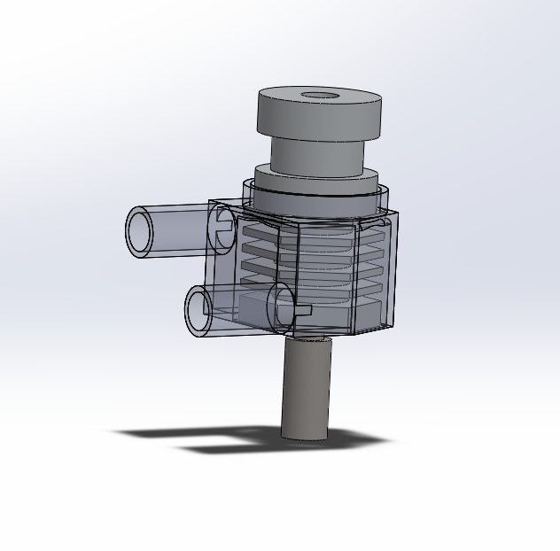
Water Cooling System Rev B

As I mentioned last time during testing I found my water cooling system for my 3D printer was way too efficient.  I've been thinking about what tweaks I might need to make to improve its functionality and today sat down to work out the details.  

The biggest change I have made has been to the amount of water interacting with the aluminum heat sink.  Before I had several fins that water flowed around, this time I've only got one channel for the water to flow around.  I have also decided to reduce the hose size that feeds the heat sink from .25 inch ID to .125 ID.  Originally I had planned to use .125 or 1/8th inch ID hose but decided to ditch the idea since it wasn't as readily available as other sizes.  Also the hose adapters to go from 5/16" to 1/8" didn’t exist but that’s not a problem really because I can make my own.  I have also decided to try to route the hoses up rather than straight out from the heat sink.  I found before the hoses had a tendency to droop below the print nozzle as the print head moved up.  This could catch on tall prints and cause major problems.

In terms of design I decided to try something new and designed in a small support block under the input/output of the water jacket.  Typically the printer will just put support material under those areas but it often leads to parts that don’t look good and are distorted to some degree.  The support blocks give the areas to be printed a solid support structure which yields less drooping and better quality.  There is enough of a gap that the block is easily removed. 

Time to make some parts and do some testing!


3D Printer Water Cooling System Testing

I came to the conclusion that the heat sink that came with the print head for my Lulzbot was not suitable for modifying for water cooling.  There just wasn’t enough material to get a reliable seal between the aluminum heat sink and the 3D printed water jacket.  So I designed my own replacement aluminum heat sink.  I retained the same overall length, decided to add some fins to optimize the heat transfer and added 3mm of surface for the aluminum heat sink and the water jacket to seal against.  I didn't bother adding O-ring groves since I wasn't sure if it would even work.  

I decided to stay after hours Friday night to get the aluminum heat sink programmed and machine one for testing over the weekend.  It actually worked out pretty great and I got one exactly to spec first try.  That doesn't happen often.  

I reworked the 3D printed water jacket to fit the new dimensions of the heat sink.  To seal all the connections I've been using Dow-Corning 732 sealant.  It’s rated for temperatures up to 177C so I feel pretty comfortable using it on the heat sink.  The water itself is probably the limiting factor in how hot the heat sink can get.  

After assembling the new heat sink and letting it dry I performed some flow testing to check for leaks.  Everything looked great.  I also ensured it could be installed into the print head without compromising the seal.  The upper seal failed on the previous iteration when the RTV upper seal tore when it was installed in the aluminum support block.

The next step, install in the printer and see if it works.  I started with just installing the cooling system and tool head and running the pump for a while just to make extra certain there were no leaks.  Everything still worked great so I decided to power up the hot end.  To test its performance I used the thermocouple of my Fluke 87 placed within the heat sink at a point just above the heat break.  This should be the hottest point of the heat sink and as long as temperatures stay cool there, the rest should be even cooler.  

At 100 degrees C the thermocouple showed a temperature increase of about 2 degrees C over ambient.  This was with the pump running at 100%.  Pleased with this result I set the temperature to 200 C (printing temperature for PLA).  It took the hot end much longer to get there but eventually it settled in at about 198 C.  Again the thermocouple showed about a 2 to 3 degree increase above ambient.  I decided to push the temperature up to 250 but ran into a problem at this point.  It turns out the heater was unable to heat the hot end beyond 200 with the pump flowing at 100%.  

I then decided to see how low the flow needed to be in order for the heater to work effectively.  To modulate the flow I used a DC power supply that gave me fairly fine control over voltage.  To help see the flow better I added some glitter to the water.  This helped me ensure that not only everything was working but also judge the waters relative velocity.  After some testing I found that my current design wicks away the heat far too efficiently for the hot end to keep up.  The bare minimum voltage that the pump would operate at seemed to be about 2.5 volts (fairly impressive) but even the tiniest trickle would cause the temperature inside the heat sink to plummet and the temperature at the hot end to follow suit.  I suppose working too well is better than not working at all!

To completely test the system I decided to do a 'dry run' print (no hot end temp or bed temp set) and see how the heat jacket stands up to the rapid movements of the printer while it was running.  It passed with flying colors and shows it can work.

I've learned many things that could help shape the next iteration.  Now I just have to go back to CAD for some tweaking for Rev C.  


Updated Fender Eliminator

Made some tweaks to my fender eliminator tonight.  Since I have a 3D printer with a much bigger build volume I can print a bracket that has the turn signals integrated into the bracket rather than having them as separate parts.  I also added some fillets and generally dressed up the appearance along with adding a logo on the top.  While it seems nicer to have it all as one piece, I learned today that having the turn signals as separate pieces has its advantages when a coworker accidently crash a box directly into the turn signal on my motorcycle and it snapped the turn signal bracket off.  This sounds bad but actually it was really easy to fix.  All that was needed was to unbolt the broken parts of the turn signal, slip the LED strip out and slip it into a new one and then bolt everything back together.  The version made all of one piece won’t be as easy to repair but I'm thinking if I print it of Alloy 910 nylon it will be much stronger.  

Then again I may just stick with the old design and print all the parts with nylon to make everything stronger than the PLA its currently made from.  Having the turn signals fail while preserving the rest of the bracket could be preferable to needing to potentially replace the whole bracket should something happen.     


Updates At The Shop

Lots of parts are getting finished up and made ready for plating.  While I didn’t make the uprights, I did debur and scotch bright them to make them ready for anodize.  I couldn’t help taking a picture of them in their milk crate, they look so shiny.  Individually they are very light but when you throw 27 all together, they get really heavy!

I was also able to get all of the bell cranks ready for the next 5 Drakan cars.  This is a fairly tedious procedure that starts with test fitting a few bearings to check the interference and make sure the hardened inserts are able to spin freely.  If they all check out I then install all the roller bearings (2 per bell crank) then grease them as they come dry.  Its amazing how much grease each little bearing needs.  Then I get the outer bearing assemblies ready.  That consists of a thrust bearing (which needs to be greased) sandwiched between two .032" steel 'shields'.  Each bell crank needs two of those.  Finally the hardened shaft goes in and the two outer aluminum 'shields' go on with X-rings attached to seal out dirt and grime.  If that all wasn't enough I then clamp the bearing assembly in a vice to simulate being bolted in place and ensure they are able to pivot freely and don’t bind.  If there is any binding between the outer aluminum shield and the bell crank as it rotates I'll pop off the shields and polish the outer edge of the shield until things dont rub.  Sometimes little burs can get left on the aluminum shields from the late operations but I took care to make sure they were all smooth and perfect before going to anodize so I really didn’t run into any problems at all.  

And finally there are always things needing more helicoils!  They don’t look quite as cool as when we use to anodize all the parts black but its still installing all of them is just one of those little things that needs to be done and takes a lot of time. 


Wet Testing!

I had some time today to build up a 'test rig' to prove the functionality of my water jacket.  Admittedly this is my second attempt at wet testing.  The first attempt involved the part printed in T-Glass material and that went south before I had done much of anything.  I ditched the T-Glass for Alloy 910 and a fine .1 mm layer height plus I tweaked the design a bit to give thicker walls to the part just to ensure there are no leaks from the walls or corners.  Turns out the Alloy 910 nylon works great!  Nylon is quickly becoming one of my favorite materials to work with.  It’s flexible rather than brittle, there are different kinds of nylon to suit particular needs and it prints very well.  I have yet to do many big parts but so far I've been pleased.    

My test rig involved my big rack mount power supply, a windshield washer reservoir/pump scavenged from a Mazda Miata (if there is one thing I have no shortage of, its Miata parts) and some tubing procured from the store.  I had to print an adapter to connect the 5mm ID tube from the pump to the 1/4" ID tube I'm using everywhere else which was no big deal.  

For the most part things worked great.  Water flowed into and out of the water jacket just as intended and there were no leaks from the water jacket itself.  The only leaks that did occur came from one of the barb fittings.  I think the leak is due to the way the printer does the two barb fittings jumping back and forth between them.  This leads to some material building up on the sides of each barb fitting which probably didn’t get cleaned off very well.  I think I might get some actual sealant to put on the barb fittings once I get hose lengths figured out so there will be no leaks at all.  

The RTV seal seemed to work great, in this static test at least.  While its really not the proper way to do a seal its quick and cheap.  I printed yet another part with tighter tolerances and made sure to clean the buildup off the sides of the barb fittings.  Since this test seems to work my next goal will be to validate that it works when attached to the heating element.  I could already tell that the flowing water really cooled down the aluminum in the part so it will be interesting to see what happens.


Updates At The Shop

More parts are getting finished and ready for the next 5 Drakan cars.  This includes bar ends for the Drakan roll hoop supports, and bell crank bushings.  

The bushings are some of the most challenging parts to make because they are made from hardened steel shafts.  There is a special drill we use to bore out the inside and then a special tool to shape the ends.  On the parting operations a finger must be kept close to the "E-Stop" button as inserts have a habit of exploding.  Three parts in I had a new insert go.  Fortunately we had a lot of inserts on hand.

With the end of lathe part manufacture I have been transitioning to putting together sub-assemblies.  I started with easy and quick stuff like adding heat shrink to the steering racks (works much better than paint to color the zinc plated tie rods) and removing the tie rod ends.  I also pressed steel inserts into steering arms and started installing helicoils into the uprights.  Orders have been placed for bearings so I can assemble the bell cranks for the cars.  

Other important parts have been showing up such as the fuel cells pictured.  One seems to be arriving every week.  I was tempted to take them out of their boxes but with a potential move approaching I decided it would be best to keep them safe in their boxes until needed.  

Design, Prototype, Test, Learn, Design...

I was able to make some prototypes for my "water jacket" as I am calling it.  They are in approximate order of their design and conception from the top left being the earliest, bottom right the latest.  I started printing parts using Blu-Print material because it is designed for 'high heat' applications.  I thought it might come out clear because the material on the spool is very clear but turns out it becomes very cloudy with the print settings I've been using.  I decided to switch to T-Glass for no other reason than I thought it would be neat to see through the part and its glass temp is also well above the measured temperatures I recorded in my testing.  

It seems the T-glass has a lot less shrinkage than the Blu-Print, just something to keep in mind.  Its not a big deal as the gaps between the material and the heat sink will allow greater thermal expansion to occur and be taken up by the silicone sealant.  

Ultimately I might make the part out of Taulman Alloy 910 because it is the strongest material I have on hand and the last thing I want to have happen is for one of the nozzles to snap off during rapid movements and have the system to disgorge all of its water on the build platform. For now however I am quite happy with the fit and appearance of the part so I think I am ready for some testing with water to see how water tight the part is.  

Another Crazy Idea

I have been reasonably impressed with my Lulzbot Taz 5's reliability and performance with the single extruder tool head, that is until it failed the other day fairly early on in a 10 hour print.  I ran the print overnight and made sure it started out ok.  I came back in the morning to find the printer just moving around in air.  Turns out the extruder jammed.

I experienced this failure mode with the dual extruder.  Somehow the filament melts and gets stuck above the heat sink.  If you try to just heat it up and extract the stuck filament nothing happens.  The only solution is to take the tool head out of the machine and drill it out.  So I bought a second single extruder and decided to use my jammed one for R&D.

Inspired by PC liquid cooling systems, I decided to see if I could design a liquid cooled tool head for my printer.  My initial thought was to use a system that didn’t have a pump and relied upon convection to keep things cool, but eventually I decided to give the pump a try since flowing fluid would carry heat away much more efficiently and cheap pump/reservoir combos are available on amazon.  

I was going to design and machine a new heat sink for the extruders but after collecting some temperature data I found the heat sink to hover around 50 to 60 degrees C which is well within the safe operating temperature of some 3D printed materials.  My idea is to have a "jacket" that slips over the heat sink and is essentially glued in place with RTV for water tightness and to allow some flex as the materials expand and cool and then have water flow into and out of the jacket keeping everything nice and cool.  It will pass through a radiator with a fan and then back into the pump.  

As far as I know I don’t think anyone has tried this (maybe for good reason).


More Mirror Updates

I made some updates and tweaks to my mirror design last night (yes, I often design things during my free time for fun).  As it turns out (not surprisingly) my 'ball and cup' pivot didn’t quite work.  The ball wasn't gripped by the cup with enough force to prevent it from rotating and eventually the force of the bolt that squeezed everything together caused the part to fail.  Can't be having that happen!

As a result I've taken what I learned from the ball and cup design and created a completely new design.  Its much more robust and allows adjustment in two axis plus rotation.  Once the desired rotation is dialed into the mirror it can be fixed by a set screw.  

Other additions and tweaks include enlarging holes for #10 hardware (since I originally designed for .125" hardware but I dont have any readily available and on second thought that’s kind of small) as well as added some logo branding to the lower left hand part of the mirror.  I don't recall if I had curved the edges of the mirror in the last post (or mentioned doing so) but the mirror body is now curved to match the curvature of the glass.  I should be getting an actual mirror delivered today so I can put more accurate numbers to the glass model I have in solidworks and print a Rev B which can actually be assembled and tested.   


Progress In the Shop

For the past few months we've been building up to complete another five Sector 111 Drakans.  This means taking inventory, finding out what we need, what we have etc.  I typically end up taking care of all the lathe parts which is a big job.  The CNC mill we have in the shop runs more or less autonomously.  As long as a part is installed properly it will do its thing, sometimes running for 45 minutes at a time or longer between part changes.  The lathe on the other hand requires constant attention.  

To start each part that is made uses a series of tools that must be manually swapped during the production.  So for example, a single part might include a spot drill, drill, internal boring, external facing then a parting operation (pretty common for most parts) which means all of those tools will have to be changed along with redirecting the coolant spray pattern to hit the cutting insert on each tool.  A run of parts can range from 5 or 6 to 250 or more which means one run of parts can require well over 1000 tool changes!  On top of that the tools ware much faster than mill tools and the length of stock in the machine causes different harmonics that cause tools to remove more or less material so it is not uncommon to have to add or subtract .001" of an inch or more every now and then to keep things dialed in.  Once they are all made they are all deburred to knock off any sharp edges and sent off to plating to be turned into beautiful finished parts.  

Fortunately all the tool changes and measuring will be coming to an end by this week or early next week.  Pictured above are the parts I've been able to check off my list over the past few days.  Suspension bushings and suspension bushing inserts were all wrapped up Monday and Tuesday.  Components for control arms and brake master cylinders (which will need to have the bore honed after plating) got checked off my list last Thursday and Friday.  I’m looking forward to no longer getting sprayed with coolant and thousand degree chips of metal, for a bit at least.