
My past experience making composite parts allows me to produce quick tooling. In this case I was able to use plaster and to create a fairly accurate negative mold. My plan was to replicate the parts using ABS plastic and heat form it into the molds. This worked great for the small brake duct half but became extremely problematic with the large brake duct half.

I was able to produce this replica of the smaller half of the brake duct fairly quickly having a part the next day however the other half of the brake duct was much larger which caused several problems with the tools quality and accuracy as well as being able to evenly heat the part and easily form it to the desired shape.
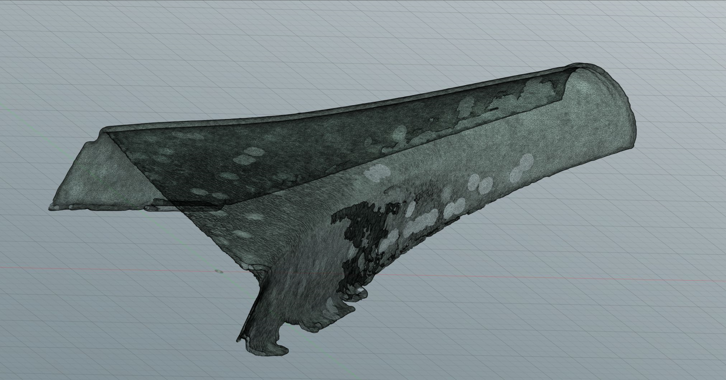
I had recently bought a 3D scanner and this seemed like a great opportunity to learn to use the 3D scanner and learn how to integrate the data into my workflow. This is the scan of the larger brake duct half.
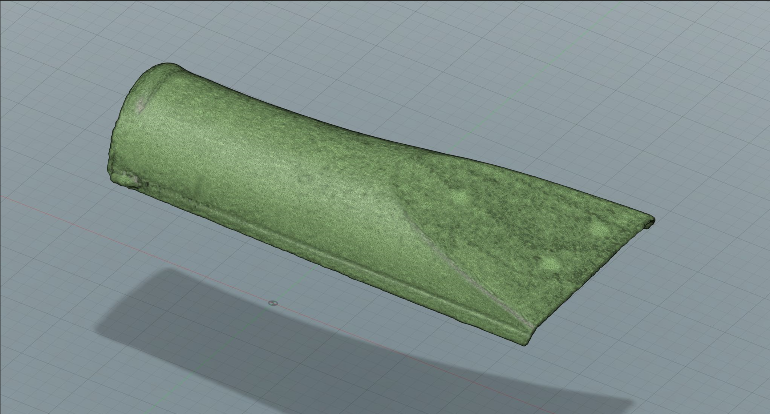
The 3D scan of the smaller brake duct half turned out really great. Its amazing how accurate the 3d scan data ended up being.
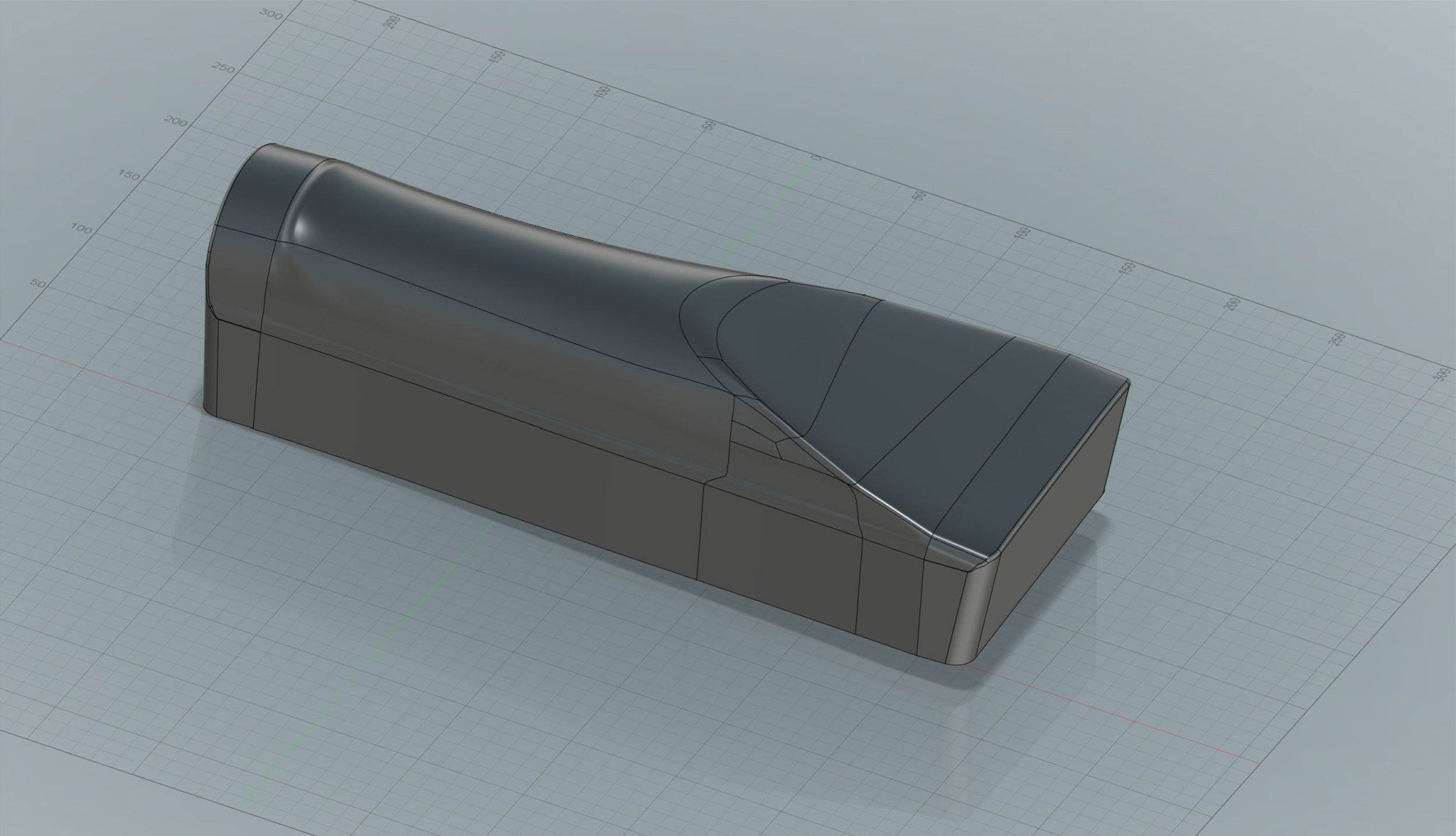
Using fusion 360 I was able to use the 3D scan data as a reference and add surfaces in CAD to eventually create the shape of the tool for a mold to create a composite replica part.
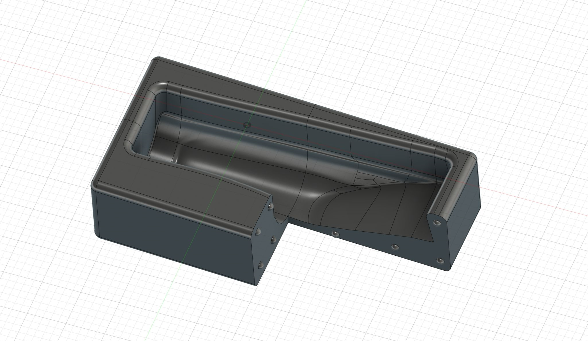
Having the shape of the tool created I then had to convert it into a separate negative mold in CAD. Keeping cost and production time low was a critical part of this project so instead of having the mold cut from foam or I decided to try 3D printing the mold. My printer wasn’t big enough to print the mold in one piece so I split the mold up into four parts and added features to allow all the parts to index against each other so they would be able to lock together accurately when assembled. Creating the mold in CAD was great since I could accurately control the shapes and radii to make laying up the part as easy as possible.

I learned from my Dodge Viper Headlight Replica project that the orientation that the mold is printed in is critical for reducing the impact layer lines will have on the part. As a result the mold for the small brake duct turned out really great with the print layers being as small and unobtrusive as possible. The indexing features allowed each part to lock together and a ratchet strap was used to keep everything together temporarily.
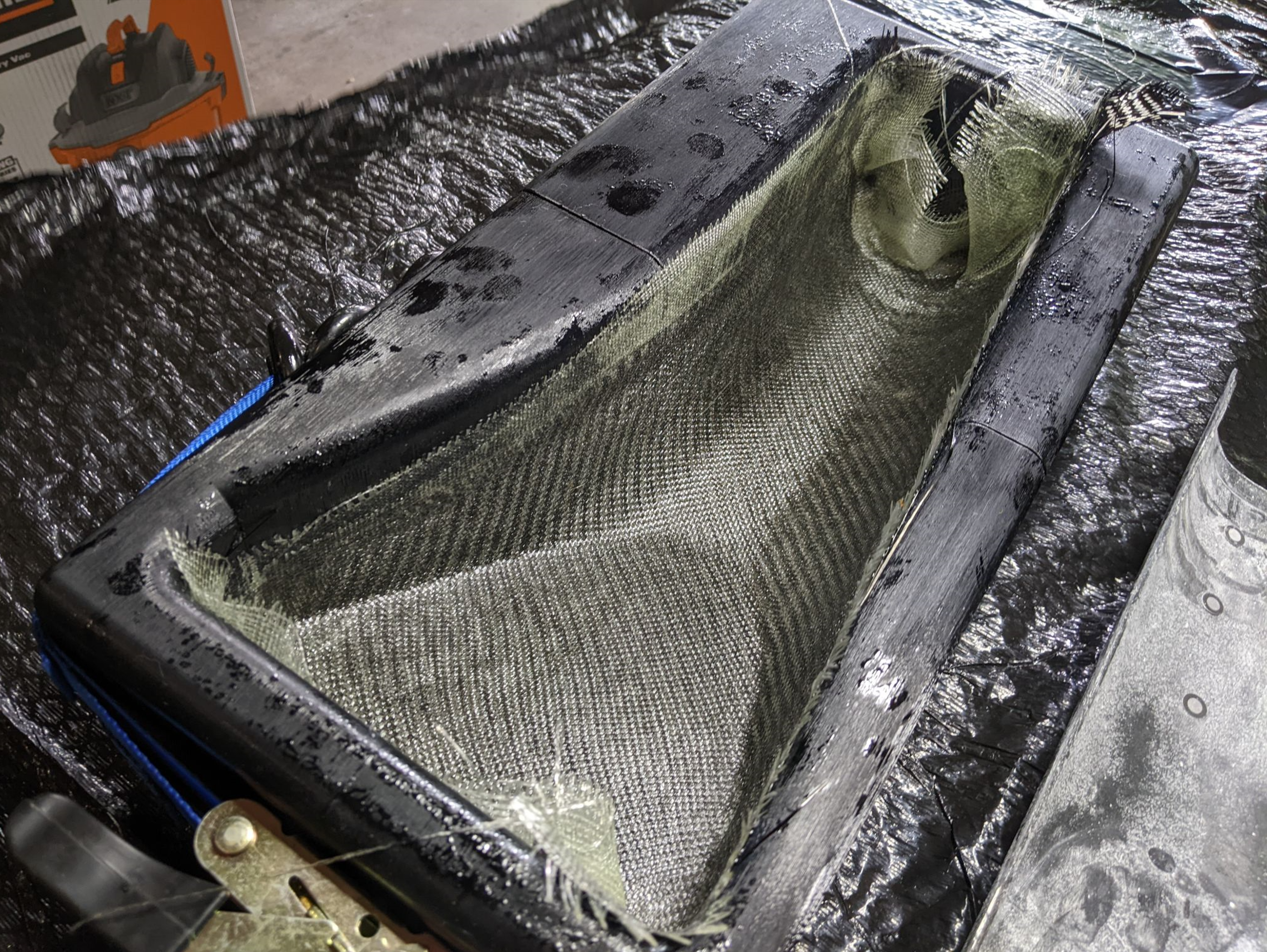
Since I was trying to keep costs as low as possible I was limited to doing a simple wet layup with two layers of carbon fiber and two layers of fiberglass. The tool worked great and all the soft edges and large run out allowed me to lay up the part fairly easily and minimize bridging and other defects.

The owners of the original part had a few brake ducts for one side of their car and wanted to prioritize making mirrored parts. Another great benefit of reverse engineering the parts in CAD was I was able to simply mirror the parts in the computer and retain all of the same accuracy. Making a mirror of a part otherwise is incredibly difficult. The part came out of the mold looking really great! There are some clear split lines from where each of the mold pieces came together and the print layers left the part with a somewhat rough finish but other than visual defects the part is really great!

Some light sanding and a layer of clear coat cleaned up the appearance of the part quite a bit. I was very happy with the results. It was now on to making the larger more complex half of the brake duct.

The large half of the brake duct was a lot more complicated. Like with the small half I started by creating surfaces in Fusion 360 using the 3D scan data for reference.
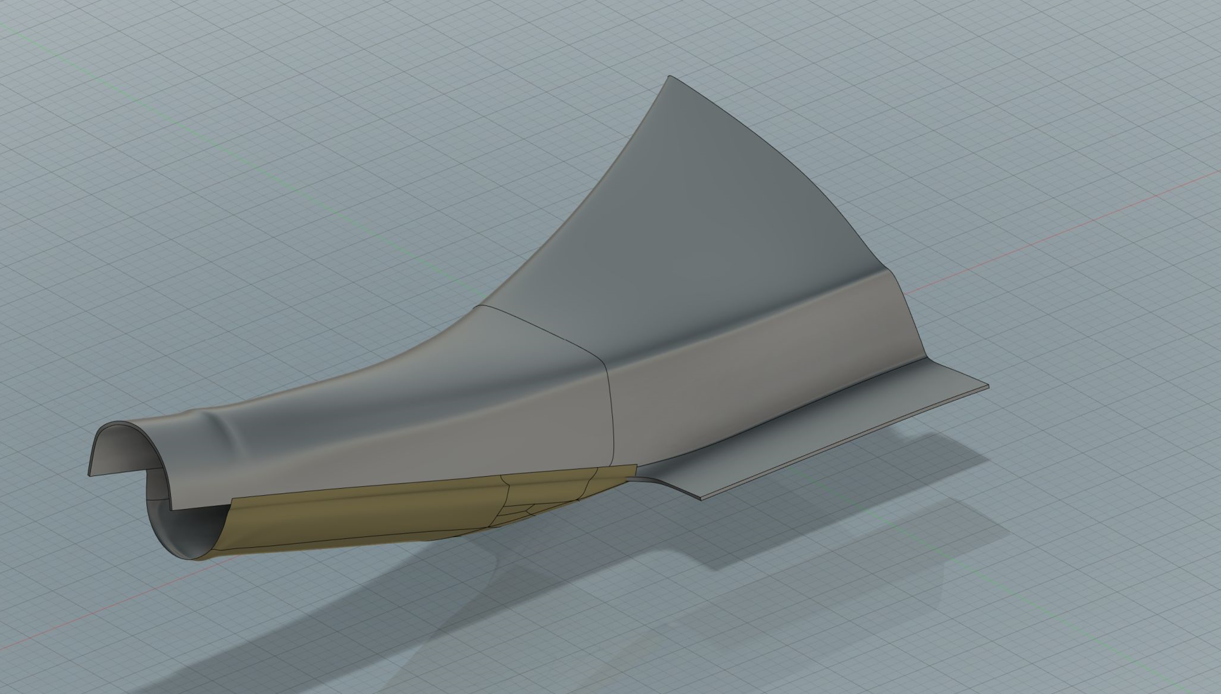
Another benefit of working with these parts in CAD is the ability to test fit them together to make sure the geometry is right. It’s a good way to build confidence that when the carbon parts are produced they will fit together and work as intended.

Once I was happy with the surfaces and shape of the part I closed off the surfaces and produced a positive tool to build the mold from. This allowed me to ensure there were generous radii and plenty of run off on the tool.

In a similar manner to the small mold I created a negative mold from the positive tool and then split it into multiple sections with indexing features to allow each section to be 3D printed and then lock together.
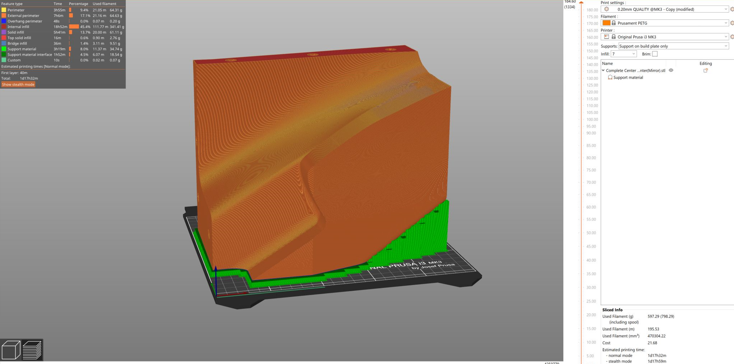
Even with the mold broken up into individual parts, each part barely fit in the build volume of my 3D printer. I was really impressed with the performance of my Prusa Mk3 and its ability to not just produce prints using its full build volume but to do it time and time again. I tried to optimize the prints as much as possible but each one was between 1 and 2 days to complete.

Another wet layup with a similar layup schedule.

The surface finish on this part wasn’t as good as the smaller half but it is still completely usable. Vacuum bagging would definitely help in the future.

The top and bottom half fit together great! This part is intended to have a brake duct hose clamped onto the end so I used multiple methods to attach the top and bottom half together. The parts were bonded together with epoxy, then rivets to ensure they were indexed correctly and finally two layers of carbon fiber was laid over the seams to give a smooth appearance.
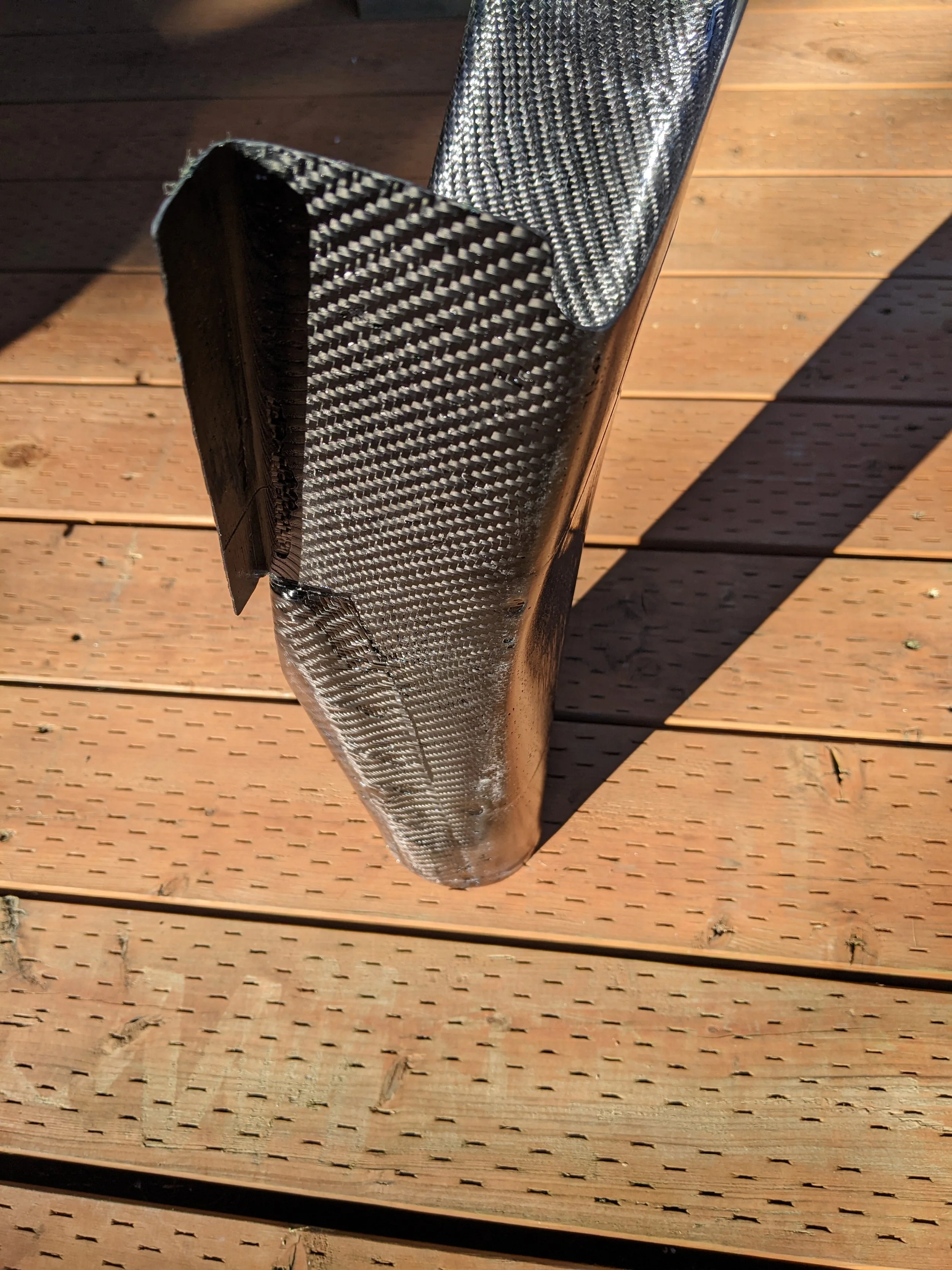
Detail of the side of the duct.

I was really pleased with the results. These are probably the most accurate composite parts I have ever created and it’s additionally impressive being a complete mirror of the original reference parts I was given.


